
Solutions by machine class
Ten classes of lifting equipment, each with its own configuration
We have configured a standard, complete solution for each of your machine classes.
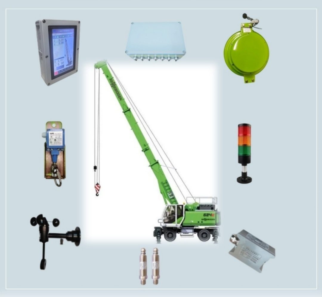
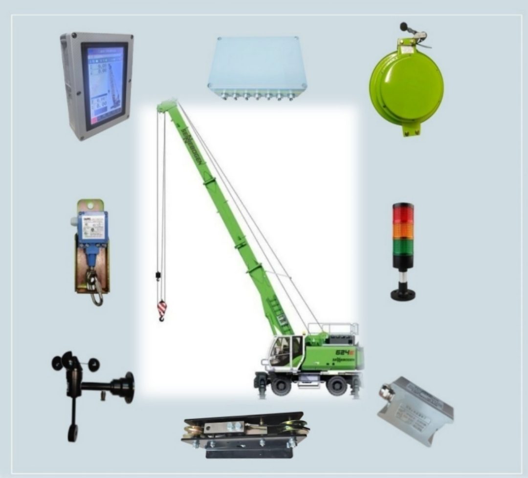
All-terrain & truck crane
System configuration
- Display
- 7 or 10 in touch screen, housing colour optional
- Control and acquisition box
- ABS or cast aluminium
- Length and angle sensor
- 15–100 m, −90° to 90°
- Pressure sensor
- 4–20 mA / 35 MPa (option)
- Load cell
- E+E-S+S- (option)
- Anemometer
- RS485 or 4–20 mA (option)
- Alarm beacon output
- 24 V DC (one channel standard, up to three)
- Hoist limit switch
- Normally open or normally closed
Ask us about further options for the jib or the auxiliary hook.
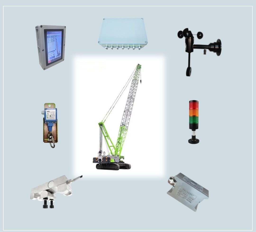
Crawler crane
System configuration
- Display
- 7 or 10 in touch screen, housing colour optional
- Control and acquisition box
- ABS or cast aluminium
- Angle sensor
- −90° to 90°
- Load cell
- E+E-S+S- (option)
- Anemometer
- RS485 or 4–20 mA (option)
- Alarm beacon output
- 24 V DC (one channel standard, up to three)
- Hoist limit switch
- Normally open or normally closed
A purpose-built all-in-one unit for this class, combining the display, control and acquisition above; ask us for details.
Ask us about further options for the jib or the auxiliary hook.
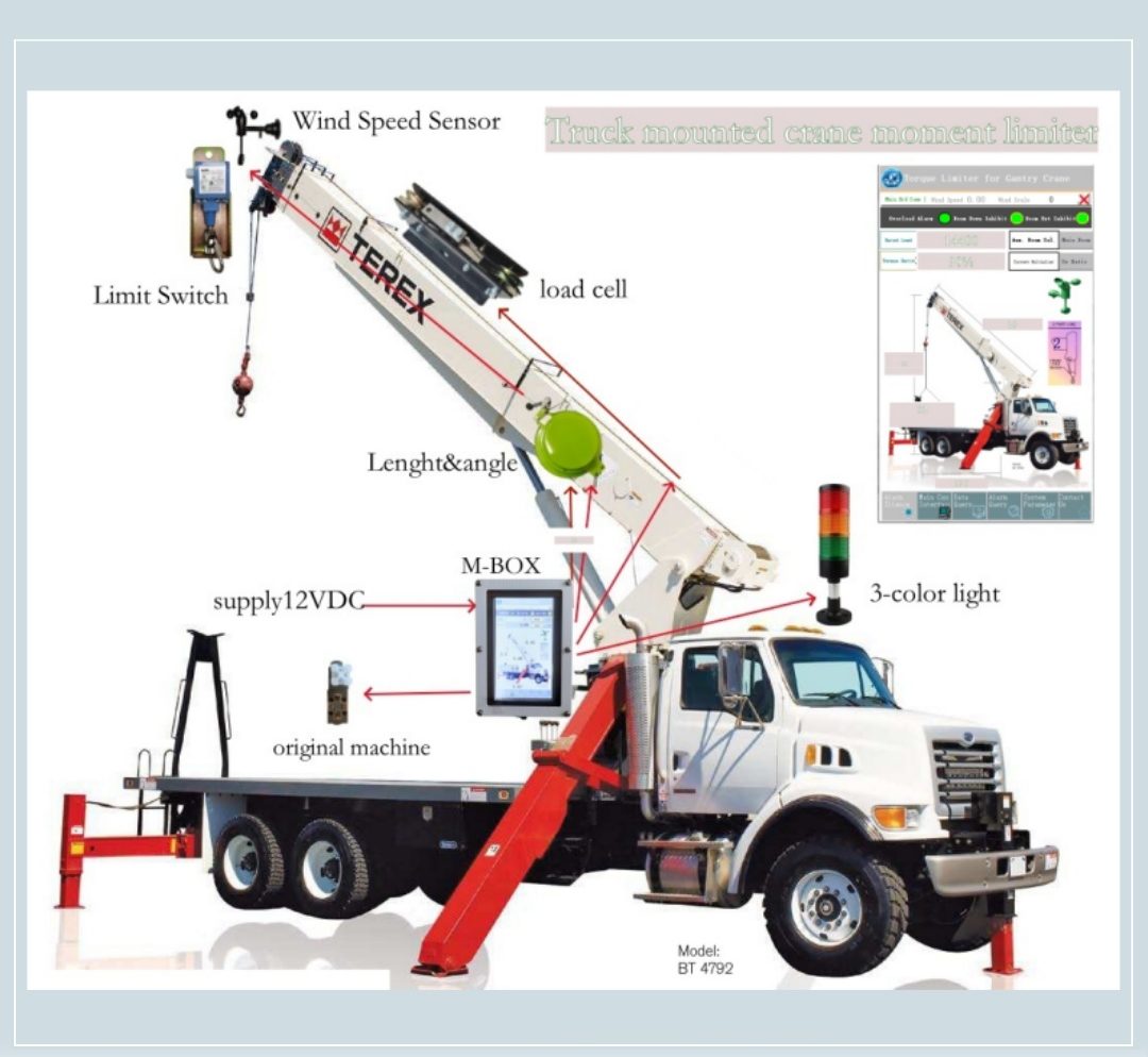
Truck-mounted loader crane
System configuration
- Display
- 7 in touch screen, housing colour optional
- Control and acquisition box
- ABS or cast aluminium
- Length and angle sensor
- 15–100 m, −90° to 90°
- Pressure sensor
- 4–20 mA / 35 MPa (option)
- Load cell
- E+E-S+S- (option)
- Anemometer
- RS485 or 4–20 mA (option)
- Alarm beacon output
- 24 V DC (one channel standard, up to three)
- Hoist limit switch
- Normally open or normally closed
- Display and host protection
- IP66
Ask us about further options for the jib or the auxiliary hook.
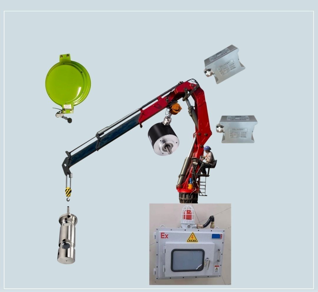
Knuckle boom crane
System configuration
- Display
- 7 or 10 in touch screen
- Control and acquisition box
- ABS, cast aluminium or stainless steel
- Length and angle sensor
- 15–100 m, −90° to 90°
- Pressure sensor
- 4–20 mA / 35 MPa (option)
- Load cell
- E+E-S+S- (option)
- Alarm beacon output
- 24 V DC (one channel standard, up to three)
- Hoist limit switch
- Normally open or normally closed
- Encoder
- RS485 (wire-rope length measurement)
For port or marine duty we provide dedicated packages — explosion-proof, salt-spray and corrosion-resistant grades — and separate configurations for the rope and ropeless types; ask us for details.
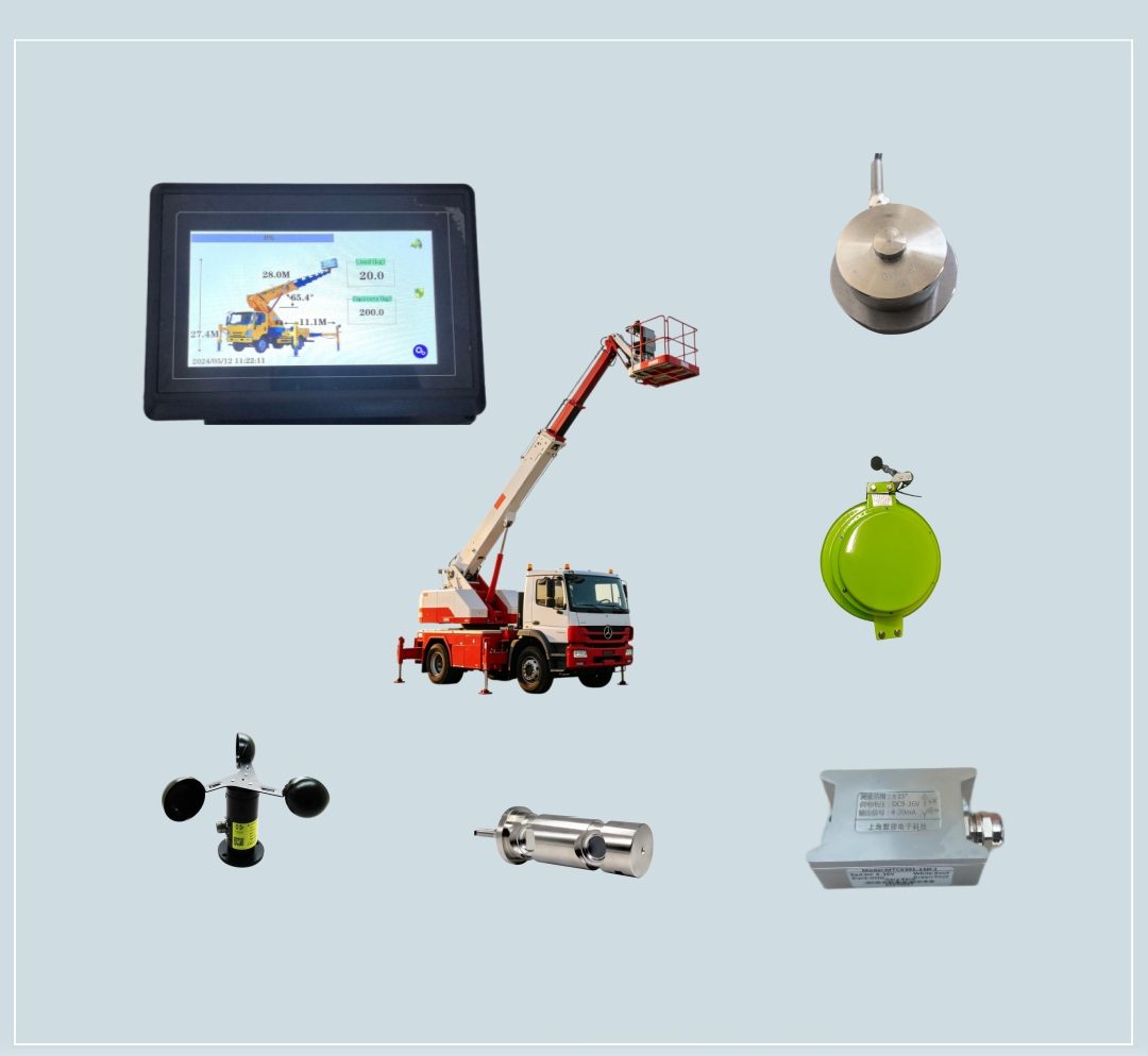
Aerial work platform
System configuration
- Display
- 7 in touch screen
- Control and acquisition box
- ABS or cast aluminium
- Length and angle sensor
- 15–100 m, −90° to 90°
- Load cell
- E+E-S+S- (option)
- Anemometer
- RS485 or 4–20 mA (option)
- Alarm beacon output
- 24 V DC (one channel standard, up to three)
- Display and host protection
- IP66
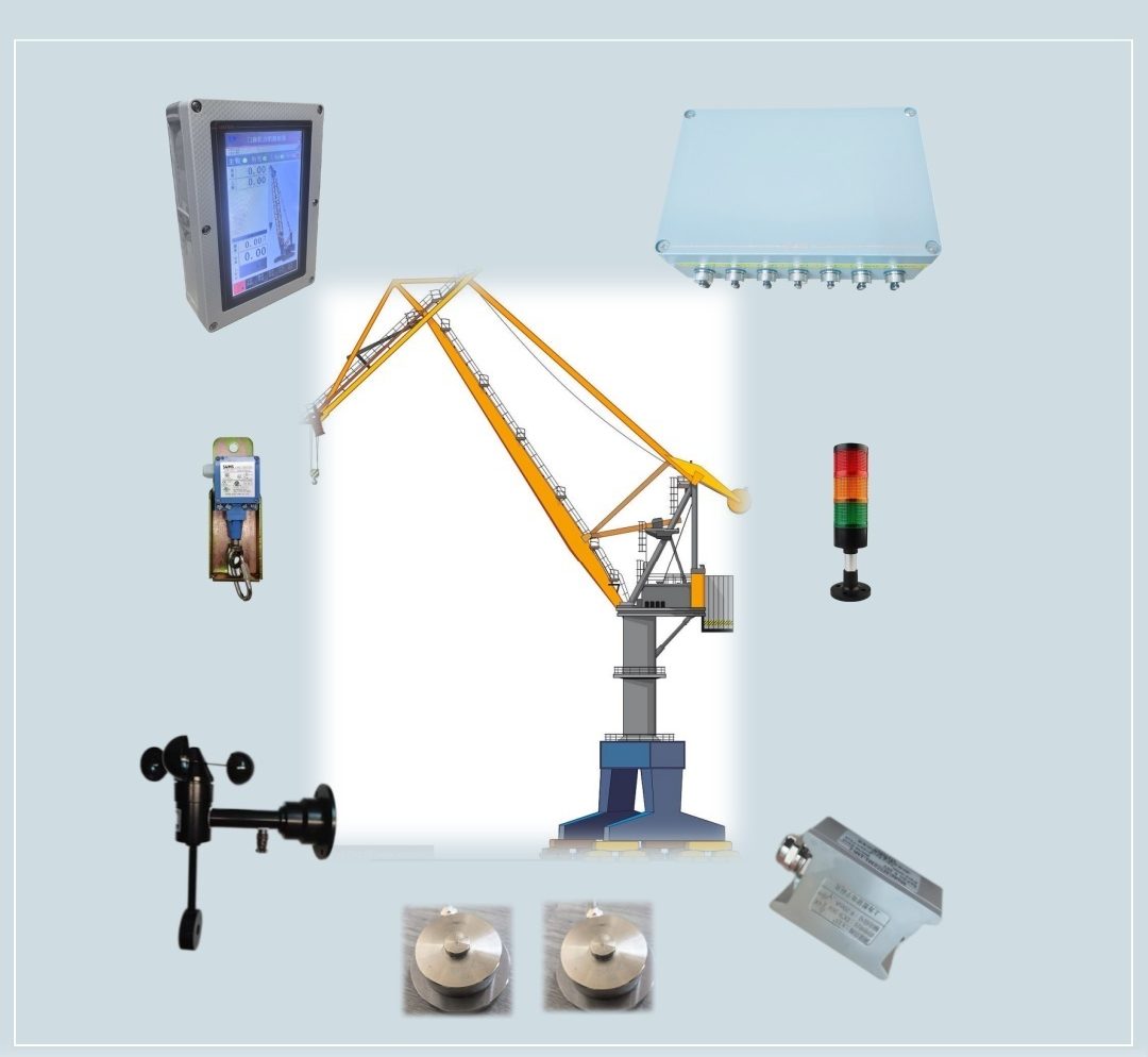
Marine & portal crane
System configuration
- Display
- 7 or 10 in touch screen, housing colour optional
- Control and acquisition box
- ABS or cast aluminium
- Angle sensor
- −90° to 90°
- Load cell
- E+E-S+S- (option)
- Anemometer
- RS485 or 4–20 mA (option)
- Alarm beacon output
- 24 V DC (one channel standard, up to three)
- Hoist limit switch
- Normally open or normally closed
A purpose-built all-in-one unit for this class, combining the display, control and acquisition above; ask us for details.
Ask us about further options for the auxiliary hook.
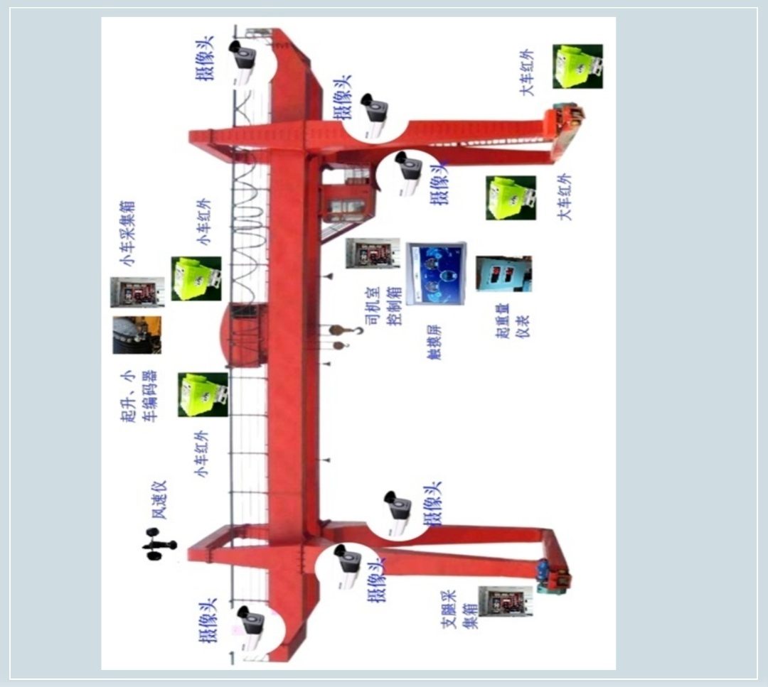
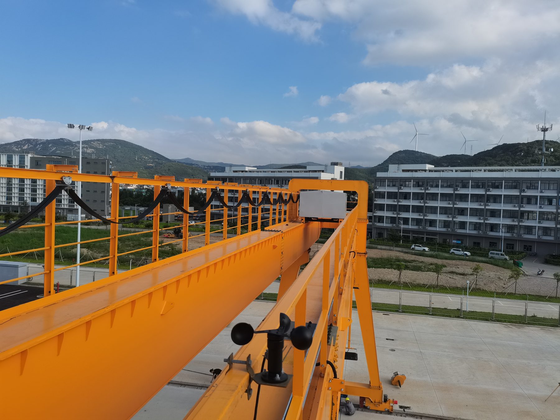
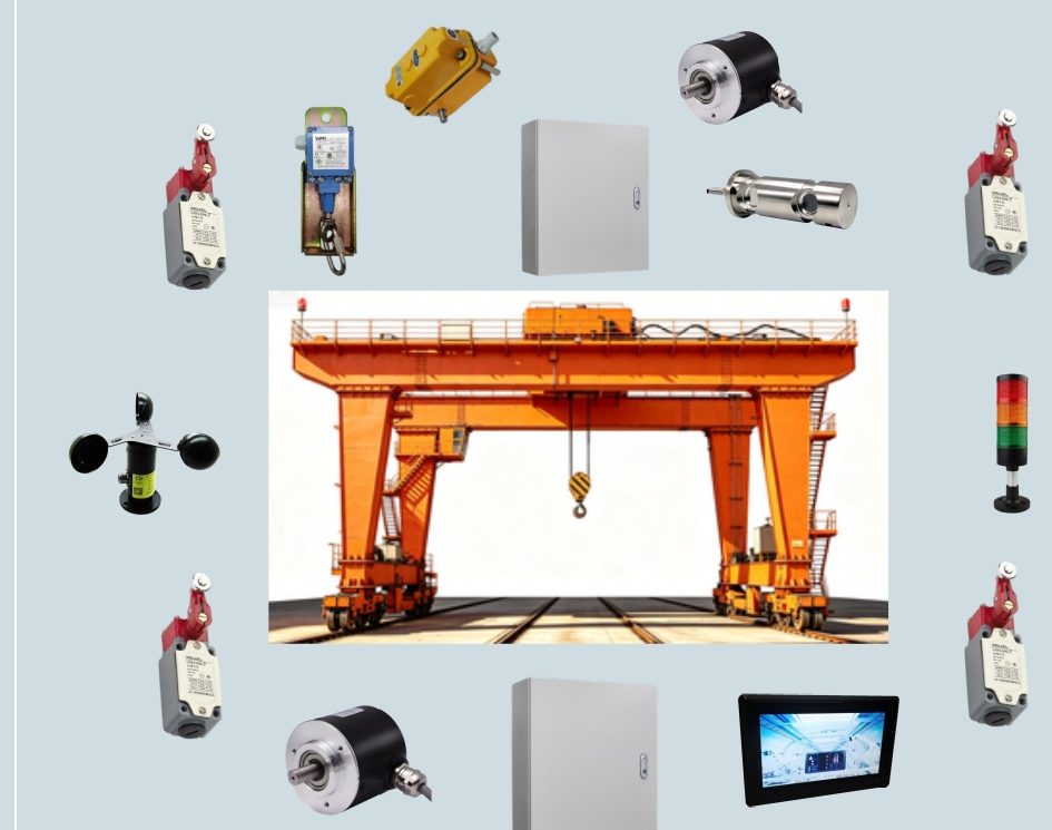
Gantry crane
System configuration
- Display
- 7 or 10 in touch screen, housing colour optional
- Control and acquisition box
- ABS or cast aluminium
- Load cell
- E+E-S+S- (option)
- Anemometer
- RS485 or 4–20 mA (option)
- Alarm beacon output
- 24 V DC (one channel standard, up to three)
- Hoist limit switch
- Normally open or normally closed
- Travel limit switch
- Normally closed (infrared type optional)
- Encoder
- RS485 or PN (long and cross travel positioning)
- Distribution box
- Metal, sized to suit
- Multi-function hoist / length / height limit switch
- 1:80 (option)
- Video monitoring system
- 1–5 CH (option)
- Hook monitoring and follow system
- (option)
Ask us for full details.
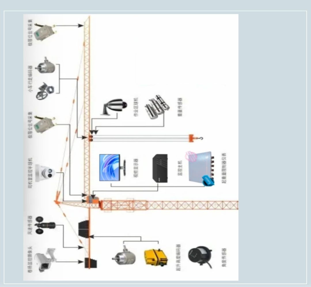
Tower crane
System configuration
- Display
- 7 or 10 in touch screen, housing colour optional
- Control and acquisition box
- ABS or cast aluminium
- Load cell
- E+E-S+S- (option)
- Anemometer
- RS485 or 4–20 mA (option)
- Alarm beacon output
- 24 V DC (one channel standard, up to three)
- Hoist limit switch
- Normally open or normally closed
- Travel limit switch
- Normally closed (infrared type optional)
- Encoder
- RS485 or PN (long and cross travel positioning)
- Distribution box
- Metal, sized to suit
- Multi-function hoist / length / height limit switch
- 1:80 (option)
- Video monitoring system
- 1–5 CH (option)
- Hook monitoring and follow system
- (option)
Black-box recording keeps a usable record for later review.
Ask us for full details.
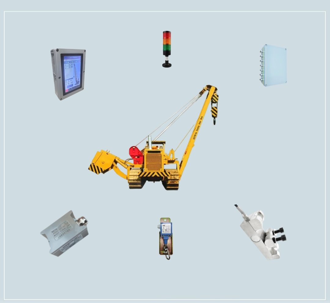
Pipelayer
System configuration
- Display
- 7 in touch screen
- Control and acquisition box
- ABS or cast aluminium
- Angle sensor
- −90° to 90°
- Load cell
- E+E-S+S- (option)
- Alarm beacon output
- 24 V DC (one channel standard, up to three)
- Hoist limit switch
- Normally open or normally closed
A purpose-built all-in-one unit for this class, combining the display, control and acquisition above; ask us for details.
Ask us about further options.
Derrick & mast crane
System configuration
- Display
- 7 or 10 in touch screen
- Control and acquisition box
- ABS or cast aluminium
- Angle sensor
- −90° to 90°
- Load cell
- E+E-S+S- (option)
- Alarm beacon output
- 24 V DC (one channel standard, up to three)
- Hoist limit switch
- Normally open or normally closed
A purpose-built all-in-one unit for this class, combining the display, control and acquisition above; ask us for details.
Ask us about further options.
More options
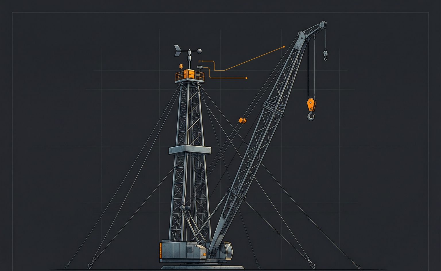
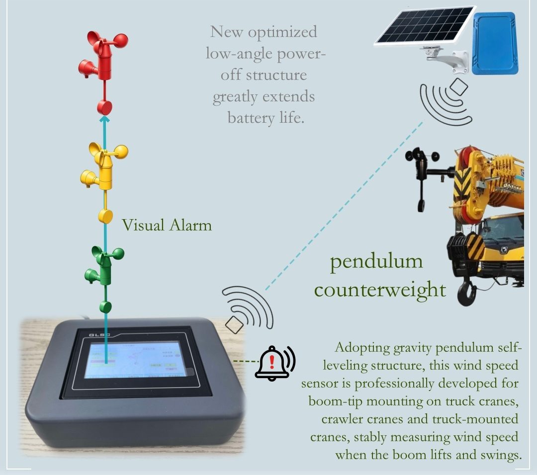
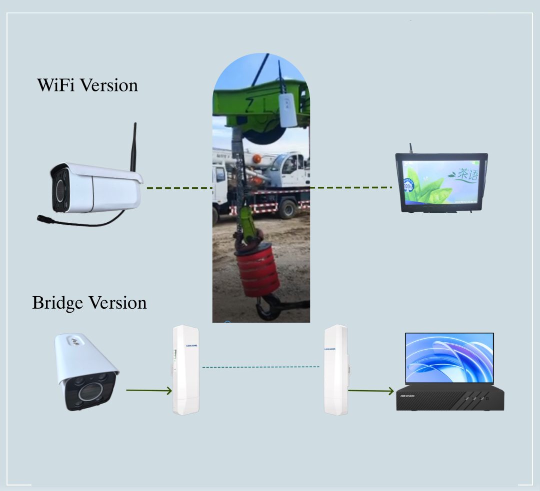
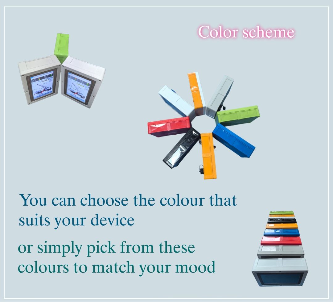
Several mounting brackets are available for your display terminal housing, with up to 8 colours to choose from, and an anemometer and a wireless camera are available for your system.

Confirm a configuration
Send a nameplate photo and the load chart. We return a configuration list with mounting positions. Model designations often straddle classes — a photo beats a name.